Hardware
The scale model: one gate and two bays on a 3D-printed car park, wired to two Arduino boards and an ESP32-CAM, run from a laptop. This page is the short version; the full step-by-step guide lives with the source code, which is kept private.
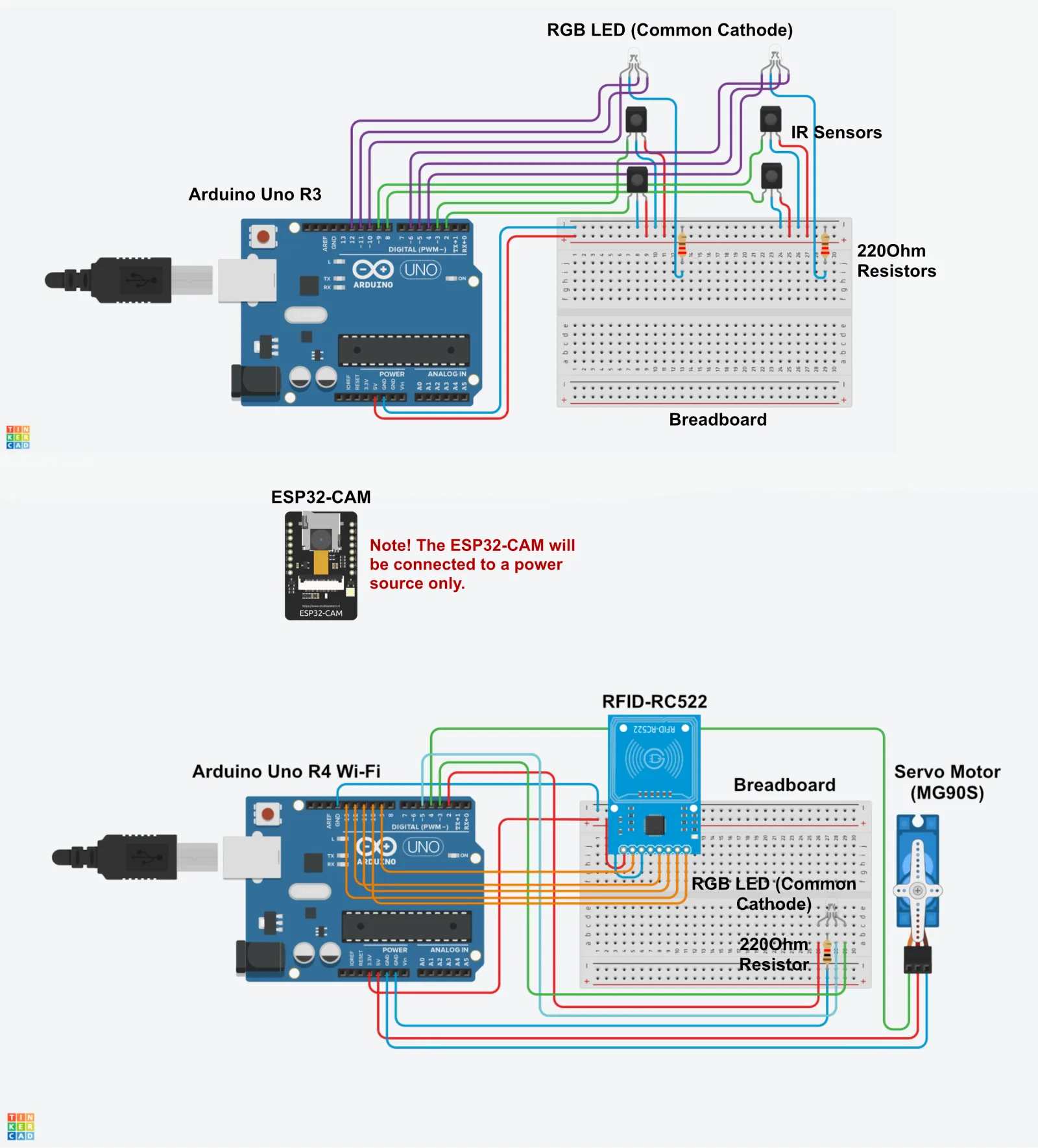
Parts
| Qty | Part | Job |
|---|---|---|
| 1 | Arduino Uno R4 WiFi | Gate controller |
| 1 | Arduino Uno R3 | Bay controller |
| 1 | ESP32-CAM (AI-Thinker) and a USB programmer for it | Plate and face camera, Wi-Fi stream |
| 1 | RFID-RC522 reader, 13.56 MHz cards or fobs | Driver's card |
| 1 | MG90S micro servo | Barrier arm |
| 4 | IR obstacle sensor modules (output LOW when blocked) | Two per bay |
| 3 | RGB LEDs, common cathode, and 3 × 220 Ω resistors | Gate light, one light per bay |
| 2 | Breadboards, jumper wires, two USB cables | Wiring, power and data |
| 1 | Laptop (macOS or Linux tested: macOS, Apple M1) | Site computer |
Wiring
Gate controller (Uno R4 WiFi)
| Part | Pin | Board pin |
|---|---|---|
| RC522 reader | SDA (SS) | D10 |
| SCK | D13 | |
| MOSI | D11 | |
| MISO | D12 | |
| RST | D9 | |
| 3.3V | 3.3V (never 5V) | |
| GND | GND | |
| RGB LED | Red / Green / Blue | D2 / D3 / D5 |
| Cathode | GND through 220 Ω | |
| MG90S servo | Signal (orange) | D4 |
| Power (red) | 5V | |
| Ground (brown) | GND |
Bay controller (Uno R3)
| Bay | IR sensor A | IR sensor B | LED red | LED green | LED blue |
|---|---|---|---|---|---|
| A1 (standard) | D2 | D3 | D4 | D5 | D6 |
| A2 (accessible) | D7 | D8 | D9 | D10 | D11 |
Sensors take 5V and GND from the board; each LED's cathode goes to GND through 220 Ω. D4 has no PWM on the Uno, so bay A1's red is on or off, which is all the light patterns need.
Flashing
With the Arduino IDE: open each sketch folder, choose the board, upload. Libraries: MFRC522 (Library Manager) and Servo (built in). From the command line:
arduino-cli compile --upload -p <port> --fqbn arduino:renesas_uno:unor4wifi firmware/gate_control
arduino-cli compile --upload -p <port> --fqbn arduino:avr:uno firmware/parking
The camera needs its Wi-Fi details first. Copy secrets.example.h to secrets.h in firmware/ESP32_CameraWebServer/ and fill it in (git ignores it), then upload with the board set to AI Thinker ESP32-CAM (esp32:esp32:esp32cam). The Serial Monitor prints the stream address.
Firmware 2.0.0 speaks the framed protocol. The first build's host program (legacy/main.py) only understands the old firmware, so flash 2.0.0 together with the new site software, not with the old program.
Bench tests
Open the Serial Monitor at 115200 baud on each board, with no site software running.
Gate
- On reset the board prints
$HELLO,GATE,2.0.0,2*.., then a heartbeat$HB,...every second. The light blinks slowly red: no computer. - Type O: the arm sweeps up and the light turns green. Without the computer it comes back down after about 3 seconds (the silence watchdog).
- Type D: the light flashes red for about 2 seconds.
- Tap a card: one
$RFID,<uid>*..line, however long you hold it there.
Bays
- On reset:
$HELLO,PARK,2.0.0,2*..; A1 green, A2 blue. - Cover sensor A of bay A1: after a moment,
$SLOT,0,PARTIAL,1,0*..and the light turns orange. Cover B too:OCCUPIED, red. - Wave a hand quickly over a sensor: nothing changes (150 ms debounce).
Whole system
.venv/bin/python -m smartparking doctor    # finds both boards and the camera, reports what is missing
.venv/bin/python -m smartparking run       # console on http://localhost:5001